Difference between revisions of "Technical Reference"
m (→Camber Angle: changed thumb to PNG (GIF was glitchy in-article as a thumbnail, was not comprehensible)) |
|||
| (4 intermediate revisions by 4 users not shown) | |||
| Line 1: | Line 1: | ||
== Mechanics of Steering and Suspension == | == Mechanics of Steering and Suspension == | ||
| − | === Steering | + | === Steering Geometry === |
“Front-end alignment” refers to the relationship between the wheels of the vehicle and its suspension and steering. These relationships are calculated using angles known as steering geometry. These angles are camber, caster, kingpin inclination; The following paragraphs cover the definitions of these angles and their effects. | “Front-end alignment” refers to the relationship between the wheels of the vehicle and its suspension and steering. These relationships are calculated using angles known as steering geometry. These angles are camber, caster, kingpin inclination; The following paragraphs cover the definitions of these angles and their effects. | ||
=== Camber Angle === | === Camber Angle === | ||
| − | [[image:Camber. | + | [[image:Camber.png|thumb|Camber Angle]] |
As viewed from the front of the vehicle, the camber angle is the degree to which the wheel tilts inward or outward It is measured in degrees and changes with the load of the vehicle and suspension movement. Positive camber is the outward tilt of the top of the wheel, and negative camber is the inward tilt. It is shown by a line drawn through the centre of the wheel and a second line drawn straight up and down. They should intersect where the tyre meets the road. Camber is a directional control angle and a tyre wearing angle. Originally, roads were built with high crowns; that is, they were high in the middle and sloped downward to the sides. A large amount of positive wheel camber was needed for the tyre to contact the road squarely. If the tyre does not set squarely on the road, it will wear on one side and will not get a good grip for positive steering control. Modern roads, however, are made flat with very little crown, so less camber is needed for this reason. Even with flat roads, some camber is generally desirable, because it moves the point of contact between the tyre and the road more directly under and closer to, the steering knuckle pivot. This makes the wheels easier to pivot and reduces the amount of road shock sent to the vehicle suspension and steering linkage when the wheels hit bumps. It also places most of the load on the larger inner wheel bearing. To avoid some bad effects, the amount of camber must be carefully considered when a vehicle is designed. If you have ever rolled a tyre by hand, you soon learned that you did not have to turn the tyre in order to turn a corner. All you had to do was tilt (camber) the tyre to one side, and it rolled around the corner like a cone. Figure below shows us “positive camber” At the left you can see the vertical centreline of the car, The wheel leans out a few degrees from the vertical centreline of the wheel. If the wheel leans inward from the vertical it’s called “Negative camber”. | As viewed from the front of the vehicle, the camber angle is the degree to which the wheel tilts inward or outward It is measured in degrees and changes with the load of the vehicle and suspension movement. Positive camber is the outward tilt of the top of the wheel, and negative camber is the inward tilt. It is shown by a line drawn through the centre of the wheel and a second line drawn straight up and down. They should intersect where the tyre meets the road. Camber is a directional control angle and a tyre wearing angle. Originally, roads were built with high crowns; that is, they were high in the middle and sloped downward to the sides. A large amount of positive wheel camber was needed for the tyre to contact the road squarely. If the tyre does not set squarely on the road, it will wear on one side and will not get a good grip for positive steering control. Modern roads, however, are made flat with very little crown, so less camber is needed for this reason. Even with flat roads, some camber is generally desirable, because it moves the point of contact between the tyre and the road more directly under and closer to, the steering knuckle pivot. This makes the wheels easier to pivot and reduces the amount of road shock sent to the vehicle suspension and steering linkage when the wheels hit bumps. It also places most of the load on the larger inner wheel bearing. To avoid some bad effects, the amount of camber must be carefully considered when a vehicle is designed. If you have ever rolled a tyre by hand, you soon learned that you did not have to turn the tyre in order to turn a corner. All you had to do was tilt (camber) the tyre to one side, and it rolled around the corner like a cone. Figure below shows us “positive camber” At the left you can see the vertical centreline of the car, The wheel leans out a few degrees from the vertical centreline of the wheel. If the wheel leans inward from the vertical it’s called “Negative camber”. | ||
| Line 43: | Line 43: | ||
* Leaf | * Leaf | ||
| − | I will only discuss coil type here as I think that is the most likely type modelled in LFS, | + | I will only discuss coil type here as I think that is the most likely type modelled in LFS. Briefly, coil springs have been around for a long time and are the most common type of spring used today, usually prevalent in rear suspension systems. |
| − | Coil springs are specially made from spring steel and heat treated to temper or add spring and strength to them. | + | Coil springs are specially made from spring steel and heat treated to temper or add spring and strength to them. They are fitted between the frame of the car and a bracket or recess on the suspension member or part of the axle. Front wheel drive cutaway showing the coil spring supports and bump stops and other parts. |
=== Stabilizer Bars === | === Stabilizer Bars === | ||
| Line 57: | Line 57: | ||
The lifting force on one side cause the stabilizer to twist like a torsion bar, creating a downward force at the opposite side. This helps to keep the frame level. | The lifting force on one side cause the stabilizer to twist like a torsion bar, creating a downward force at the opposite side. This helps to keep the frame level. | ||
| + | |||
| + | |||
| + | Okay, some of the above is confusing and misleading, I don't want to completely remove it though, so I'll just make my own explanation of how I understand a stabilizer bar to work. | ||
| + | |||
| + | A stabilizer bar is a torsion bar (spring) which transfers load from one side of the vehicle to the other. For example, on entering a left-hand corner, the car will lean to the right and compress the spring on the right of the vehicle. The stabilizer bar is lifted on the right-hand side, and transfers some of this lift (depending on its stiffness) to the left-hand spring, compressing it, which acts to reduce the amount of body-roll. | ||
| + | |||
| + | When travelling in a straight line, a stabilizer bar is actually useless, as a bump that only one wheel hits will transfer to the other side as well, which isn't really helpful. However, when travelling in a straight line, handling isn't a problem, so it's a small price to pay for better cornering. | ||
=== IFS (Independent Front Suspension) === | === IFS (Independent Front Suspension) === | ||
| Line 78: | Line 85: | ||
=== Double Wishbone === | === Double Wishbone === | ||
[[Image:Susp1.gif|Double Wishbone]] | [[Image:Susp1.gif|Double Wishbone]] | ||
| + | |||
| + | {{Guides}} | ||
<!-- links to other languages --> | <!-- links to other languages --> | ||
[[de:Technische Referenz]] | [[de:Technische Referenz]] | ||
Latest revision as of 11:44, 22 January 2024
Mechanics of Steering and Suspension
Steering Geometry
“Front-end alignment” refers to the relationship between the wheels of the vehicle and its suspension and steering. These relationships are calculated using angles known as steering geometry. These angles are camber, caster, kingpin inclination; The following paragraphs cover the definitions of these angles and their effects.
Camber Angle
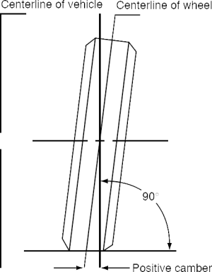
As viewed from the front of the vehicle, the camber angle is the degree to which the wheel tilts inward or outward It is measured in degrees and changes with the load of the vehicle and suspension movement. Positive camber is the outward tilt of the top of the wheel, and negative camber is the inward tilt. It is shown by a line drawn through the centre of the wheel and a second line drawn straight up and down. They should intersect where the tyre meets the road. Camber is a directional control angle and a tyre wearing angle. Originally, roads were built with high crowns; that is, they were high in the middle and sloped downward to the sides. A large amount of positive wheel camber was needed for the tyre to contact the road squarely. If the tyre does not set squarely on the road, it will wear on one side and will not get a good grip for positive steering control. Modern roads, however, are made flat with very little crown, so less camber is needed for this reason. Even with flat roads, some camber is generally desirable, because it moves the point of contact between the tyre and the road more directly under and closer to, the steering knuckle pivot. This makes the wheels easier to pivot and reduces the amount of road shock sent to the vehicle suspension and steering linkage when the wheels hit bumps. It also places most of the load on the larger inner wheel bearing. To avoid some bad effects, the amount of camber must be carefully considered when a vehicle is designed. If you have ever rolled a tyre by hand, you soon learned that you did not have to turn the tyre in order to turn a corner. All you had to do was tilt (camber) the tyre to one side, and it rolled around the corner like a cone. Figure below shows us “positive camber” At the left you can see the vertical centreline of the car, The wheel leans out a few degrees from the vertical centreline of the wheel. If the wheel leans inward from the vertical it’s called “Negative camber”.
Positive camber compensates for the weight of the car. When the car begins to move forward, the weight of the vehicle pulls the wheels into perfect vertical position. If you adjust the alignment with negative camber the wheels would be pulled in even further towards the vehicle.
Caster Angle
When viewed from the side of the wheel, the caster angle is the degree to which the kingpin or ball joint tilts forward or rearward in relation to the frame Like the camber angle, the caster angle is also measured in degrees. It is shown by a line drawn straight up and down, as in the figure and then a second line drawn through the centre of the kingpin or pivot points. The caster angle is the angle formed at the point where the two lines cross, as viewed from the side of the vehicle. A good example of caster is a bicycle. The fork is tilted backward at the top. A straight line drawn down through the front-wheel pivot or kingpin would strike the ground ahead of the point where the tyre contacts the road. A wheel mounted in this fashion is said to have positive (+) caster or “just” caster. If the top of the kingpin is tilted forward so that a straight line drawn through it hits behind the point where the tyre contacts the ground, the wheel is said to have negative (–) caster. On a vehicle with axle suspension, caster is obtained by the axle being mounted so that the top of the steering knuckle or kingpin is tilted to the rear. On a vehicle with independent suspension, the upper pivot point (ball joint) is set to the rear of the lower pivot point. Caster is a directional control angle, but not a tyre wearing angle. Positive caster causes the vehicle to steer in the direction in which it is moving. This is called an automatic steering effect; for instance, the forward momentum of a vehicle tends to keep wheels with positive caster in the straight-ahead position. After rounding a turn, this causes the wheels to return to a straight-ahead position when the driver releases the steering wheel. This automatic steering effect is also called self-righting or self-centring action. Positive caster makes the turning of the steering wheel more difficult, whereas negative caster turns more easily, but will cause the vehicle to wander. Caster is the tilting of the front steering axis either forward or backward from vertical as viewed from the side of the car see below.
When the axis is tilted backwards from vertical, caster is said to be positive. Positive caster creates a trailing action on front wheels. When the axis is tilted forward, caster is negative, causing a leading action on front wheels.
Steering Axis Inclination
This is the geometric relationship between the Ball Joints and the wheel. Note: The lower ball joint is farther out from the centreline of the car than the upper ball joint.
By drawing an imaginary line between the ball joints and measuring the angle this makes with the true centreline of the wheel, you can determine the angle of steering inclination or the angle the ball joints incline away from centre. The angle of the inclination provides a number of benefits to steering. It increases tyre life, When turning a corner it increases the rate of recovery... When the car is moving forward it makes the steering more stable, but increases the effort required to move the steering wheel.
Tracking: The greatest effect steering axis inclination has on the car is tracking. This is the tendency for the car to go where the front is pointed. This is the result of what happens when the steering knuckle moves. Because of the angle of inclination, when the steering knuckle turns, it tends to lift the car.
The weight of the car forces the axle (Steering knuckle) downward or back into a straight or horizontal angle. This pulls the wheel / tyre back into a line with the body of the car. The car continues the same way it was going.
Shock Absorbers
A bit of background information to help you understand what it does.
Although not a spring in itself, shockies are an integral part of the spring action, damping the actions of the actual spring, shock absorbers are exactly that, they are devices designed to absorb the shock or bounce generated by bumps. They reduce the action and reactions to fewer contractions and expansions of the coil. This helps to prevent the car from “floating” or the bouncing motion after it hits a bump.
If we have no shock absorbers attached to each wheel to control the compression and expansion of the coil spring, the spring would keep bouncing up and down like a rubber ball till all the energy had been dissipated. A shock absorber is filled with fluid or gas, a plunger connected to the top of the shock, is forced down when the spring compresses.
Through a series of valves, the fluid in front of the plunger is forced into side chambers, slowing or damping, the return of the spring.
Its this alternating up and down motion of the plunger that provides the required damping effect.
Springs
There are 4 basic types of spring systems used in modern cars:
- Coil
- Torsion bar
- Air springs
- Leaf
I will only discuss coil type here as I think that is the most likely type modelled in LFS. Briefly, coil springs have been around for a long time and are the most common type of spring used today, usually prevalent in rear suspension systems.
Coil springs are specially made from spring steel and heat treated to temper or add spring and strength to them. They are fitted between the frame of the car and a bracket or recess on the suspension member or part of the axle. Front wheel drive cutaway showing the coil spring supports and bump stops and other parts.
Stabilizer Bars
Or sway bars as we sometimes call them are not really springs but act as though they were springs. And help in controlling spring action. Confused? Lets look at the diagram and the explanation in more detail.
Sway bars reduce body roll on cornering, perhaps it’s best to describe them as a kind of torsion bar. They reduce some of the twisting action of the frame.
When the car moves down the road with the frame level, the stabilizer bar is at rest. When one side of the frame of the car rises up, like when it hits a bump, the opposite side of the frame rises also.
This movement is counteracted by the stabilizer bar.
The lifting force on one side cause the stabilizer to twist like a torsion bar, creating a downward force at the opposite side. This helps to keep the frame level.
Okay, some of the above is confusing and misleading, I don't want to completely remove it though, so I'll just make my own explanation of how I understand a stabilizer bar to work.
A stabilizer bar is a torsion bar (spring) which transfers load from one side of the vehicle to the other. For example, on entering a left-hand corner, the car will lean to the right and compress the spring on the right of the vehicle. The stabilizer bar is lifted on the right-hand side, and transfers some of this lift (depending on its stiffness) to the left-hand spring, compressing it, which acts to reduce the amount of body-roll.
When travelling in a straight line, a stabilizer bar is actually useless, as a bump that only one wheel hits will transfer to the other side as well, which isn't really helpful. However, when travelling in a straight line, handling isn't a problem, so it's a small price to pay for better cornering.
IFS (Independent Front Suspension)
Control Arm or Independent Front Suspension allows the two wheels to move up and down independently of each other the diagram above shows how the wheel can move up and down yet not move the frame allowing the tyre to have a level, full contact area.
This is the most common form of front suspension in modern cars and the method LFS is likely modelled upon. Solid axles are generally used in Vintage and Veteran cars and some larger trucks.
The solid axle as shown in the other diagram behaves in the opposite way. I.E. When a tyre hits a bump the whole axle and the frame will lift up, Tilting the opposite wheel and allowing the tyre to lose some contact with the road surface. McPherson Strut type front suspension is a somewhat different approach using a control arm method.
You will see there is no upper control arm present.
Everything else is there: Spring, shock stabilizer and the torsion rod. Being lighter than a normal approach its ideal for smaller cars. With the heavy duty shock and lighter spring the upper control arm is no longer needed.
Suspension Types
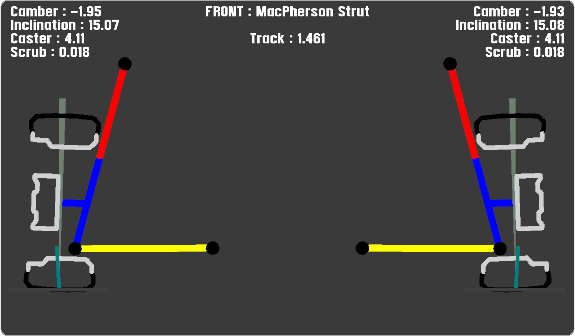
MacPherson
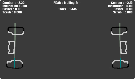
Trailing Arm
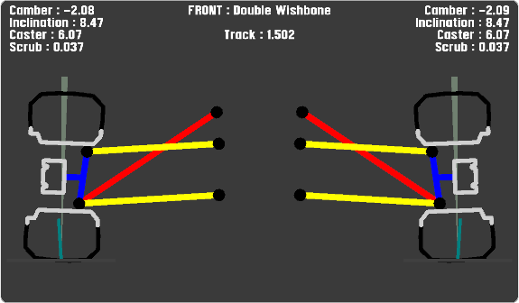
Double Wishbone


