Difference between revisions of "LFS Editor/Modeller"
m (add stub sections for editing modes & view options) |
(Vehicle model structure - points, edges, triangles) |
||
| Line 45: | Line 45: | ||
# modeller [[#View modes|view modes]] & [[#View options|view options]] | # modeller [[#View modes|view modes]] & [[#View options|view options]] | ||
# [[LFS Editor User Interface#View controls|common editor view controls]] | # [[LFS Editor User Interface#View controls|common editor view controls]] | ||
| + | |||
| + | == Vehicle model structure == | ||
| + | |||
| + | Modeller uses 3D meshes to represent the vehicle model in 3D space. All meshes are built from three basic structures - points, edges and triangles. | ||
| + | |||
| + | [[Image:LFS editor mesh parts.jpg]] | ||
| + | |||
| + | === Points === | ||
| + | |||
| + | The most elementary part of a 3D model is the point (also referred to as a vertex) which is a single point in 3D space. Points are represented in the 3D viewport in [[#Point|point mode]] as small square buttons. | ||
| + | |||
| + | === Edges === | ||
| + | |||
| + | An edge always connects two points by a straight line. They are used to construct triangles. Edges are represented in 3D viewport in [[#Tri|tri]] and [[#Point|point]] modes as thin lines. | ||
| + | |||
| + | === Triangles === | ||
| + | |||
| + | Triangles (often abbreviated to tris) are used to build the actual surface of the object. They are what you see when you render the mesh. If this area does not contain a face, it will simply be transparent or nonexistent in the actual model. | ||
| + | |||
| + | A triangle is defined as the area between three points, with an edge on every side. | ||
== Editing modes == | == Editing modes == | ||
Revision as of 18:26, 6 October 2022
| Vehicle Mods | |
|---|---|
| Vehicle Mods at LFS.net |
| This page or section is being initially created, or is in the process of an expansion or major restructuring. You are welcome to assist in its construction by editing it. |
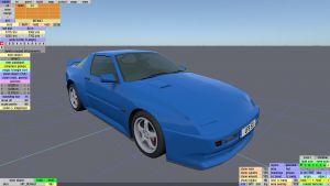
The Modeller is a part of the LFS Editor. It is used to edit the 3D model, which includes editing the mesh and applying textures.
For user guides and walkthroughs for various modeller features, see Modeller Guides.
Requirements
To be able to use the modeller, you must have an S3 license. To get the S3 license, you can visit the LFS shop page.
Starting the modeller
First, follow the instructions how to download and install the LFS Editor.
Once you have the editor installed and run the LFS Editor application, you will be presented with the entry screen. Click the Modeller button to enter the Modeller.
The modeller can also be entered from the Vehicle Editor by pressing E or clicking the E - Edit Model button on the right hand side of the vehicle editor.
General modeller tips
- The list of colours at the bottom left in 'tri' mode is a different view of the list of mappings in 'map' mode.
- When you select a triangle, its colour is selected in the bottom left list. If the list is long, click cols : X to bring the selected colour onto screen.
- In 'subob' mode you can select a subobject with Ctrl + click while pointing at one of its surfaces.
- In 'tri' mode, Ctrl + click adds or removes triangles from the selection. Alt + click starts a new selection (one triangle).
- In the special view modes (like groups or mappings) the group select feature (Ctrl + ⇧ Shift + click) does a flood select within the group.
- Press ⇧ Shift + F to temporarily hide the editor buttons.
- To reduce clutter, use hide selected to temporarily hide points and triangles, then unhide all to show the again.
User interface
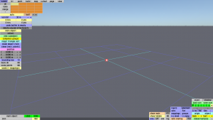
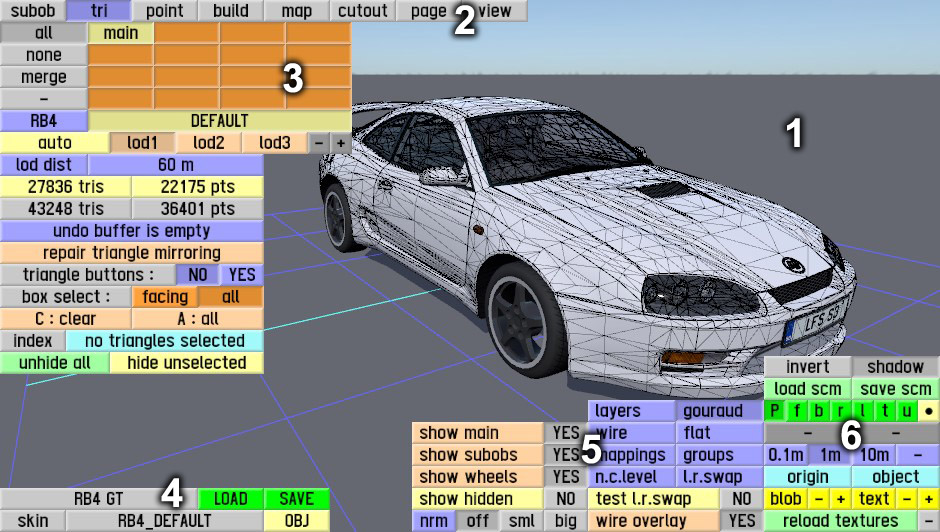
When you open the Modeller, the user interface looks as follows:
The interface consists of the following parts:
- 3D model view
- editing mode selector
- editing mode specific controls
- load / save object
- modeller view modes & view options
- common editor view controls
Vehicle model structure
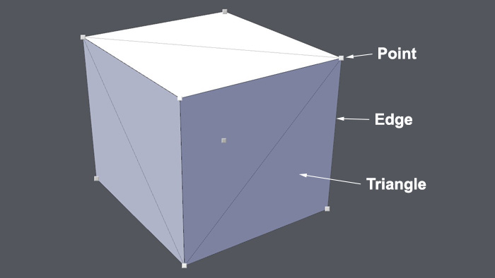
Modeller uses 3D meshes to represent the vehicle model in 3D space. All meshes are built from three basic structures - points, edges and triangles.
Points
The most elementary part of a 3D model is the point (also referred to as a vertex) which is a single point in 3D space. Points are represented in the 3D viewport in point mode as small square buttons.
Edges
An edge always connects two points by a straight line. They are used to construct triangles. Edges are represented in 3D viewport in tri and point modes as thin lines.
Triangles
Triangles (often abbreviated to tris) are used to build the actual surface of the object. They are what you see when you render the mesh. If this area does not contain a face, it will simply be transparent or nonexistent in the actual model.
A triangle is defined as the area between three points, with an edge on every side.
Editing modes
| This page or section is being initially created, or is in the process of an expansion or major restructuring. You are welcome to assist in its construction by editing it. |
Subob
Subobject mode
Tri
Triangle mode
Point
Build
Map
Cutout
Page
View
View modes
In the bottom right part of the screen, you can choose different view modes of the model:
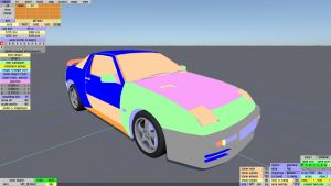
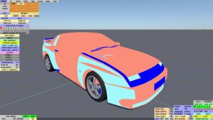
Layers
Each colour represents triangles assigned to a particular layer. You can toggle layers on/off by clicking the layer buttons in the top left part of the screen.
Wire
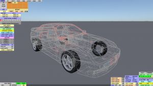
Shows the edges as a wireframe. The edges can have different colours:
- grey - two triangles share the edge. This is the normal condition for most edges in an object.
- red - an unshared edge - only one triangle uses this edge.
- cyan - three triangles share the edge.
- orange - four triangles share the edge.
When you see an edge that is not grey, it may be intentional or it may draw your attention to a bug in the model. There are reasons to have unshared edges or multiple shared edges in some cases. But if it is not intentional, it may indicate a modelling error such as:
- A double built triangle - this would appear as a cyan triangle where you expect grey triangles.
- A triangle connected to the wrong vertex - could cause unshared edges.
It's good to click wire mode occasionally and if you see edges that are not grey, make sure that you know the reason for them and that they are as intended.
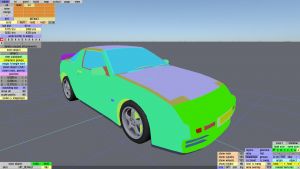
Mappings
Each colour represents a different mapping.
Flat
Flat shading of the triangles without being smoothed.
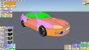
Groups
Smoothing groups. The boundaries between different smoothing groups usually have a sharp edge. All triangles within one smoothing group have artificial smoothing applied.
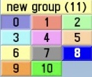
When you switch to the groups view mode and select tri mode, an additional set of buttons will be shown in the top right corner of the screen.
Each smoothing group is represented by a number and a distinct colour.
If needed, you can create new groups by clicking the new group (N) button, where N is the number of the group to be created.
You can create up to 23 groups for the model.
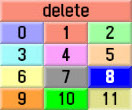
When you select a group which is not assigned to any triangles, a delete button appears at the top, allowing you to delete unused groups:
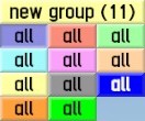
When you press and hold Ctrl, the labels of the group buttons will say all. If you click one of them, all triangles assigned to that group will be selected.
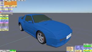
Gouraud
The default rendering of the model with gouraud shading applied. This is how the car should appear in game.
N.C.level
Normal contribution levels. Each triangle meeting at a vertex, within the same smoothing group, contributes to the normal of that surface at that vertex. In fact, large triangles have a larger contribution. So for example you could make a simple "hardback book" shaped object and most of the apparent curvature would be on the spine of that book. But the spine would still be contributing to the normals, so the front and back faces of the "book" would still be a little curved. If, however, you set the normal contribution level" of the spine to zero, then the spine would not contribute to the normals at all. Then the front and back face of the book would look totally flat.
L.R.swap
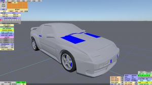
Driver swap modes. The triangles can have different colours:
- grey - applied to mirrored triangles, which do not have any swapping
- blue (static) - do not change sides when driver side is swapped
- red (swap) - change sides when driver side is swapped
In this mode, you can set driver swap modes to triangles by going to the tri mode, selecing one or more triangles and clicking one of the swap mode buttons in the top right corner.
View options
| This page or section is being initially created, or is in the process of an expansion or major restructuring. You are welcome to assist in its construction by editing it. |
Show main
Show subobs
Show wheels
Normals
Test L.R.swap
Wire overlay
Load / save object
At the bottom left of the screen, there is a set of buttons used to load or save an object in the Modeller.
If you have an subobject selected, another row of buttons appears, allowing you to load or save the current subobject.
| subobject | Indicates that a subobject is currently selected |
| load | Load a new subobject, replacing the selected subobject |
| save | Save the current subobject as an object in data\3dob |
| main object | The name of the main object |
| LOAD | Load a new object from data\3dob |
| SAVE | Load the main object to data\3dob |
| skinXFG_DEFAULT | Click the skin name (e.g. XFG_DEFAULT) to select a JPG image in data\skins to use as a skin in the editor |
