LFS Editor/Modeller
| LFS Editor | |
|---|---|
|
|
| Vehicle Mods |
Modeller is a part of the LFS Editor. It is used to edit the 3D model, which includes editing the mesh and applying textures.
Requirements
To be able to use the modeller, you must have an S3 license. To get the S3 license, you can visit the LFS shop page.
Entering the modeller
First, follow the instructions how to download and install the LFS Editor.
Once you have the editor installed and run the LFS Editor application, you will be presented with the entry screen. Click the Modeller button to enter the Modeller.
The modeller can also be entered from the Vehicle Editor by pressing E or clicking the E - Edit Model button on the right hand side of the vehicle editor.
General modeller tips
- The list of colours at the bottom left in 'tri' mode is a different view of the list of mappings in map mode.
- When you select a triangle, its colour is selected in the bottom left list. If the list is long, click cols : X to bring the selected colour onto screen.
- In 'subob' mode you can select a subobject with Ctrl + click while pointing at one of its surfaces.
- In 'tri' mode, Ctrl + click adds or removes triangles from the selection. Alt + click starts a new selection (one triangle).
- In the special view modes (like groups or mappings) the group select feature (Ctrl + ⇧ Shift + click) does a flood select within the group.
- Press ⇧ Shift + F to temporarily hide the editor buttons.
- To reduce clutter, use hide selected to temporarily hide points and triangles, then unhide all to show the again.
User interface
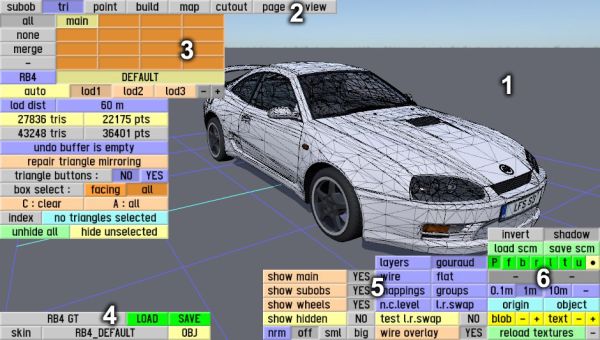
The modeller interface consists of the following parts:
- 3D model view
- editing mode selector
- editing mode specific controls
- load / save object
- model view modes and view options
- common editor view controls
Vehicle model structure
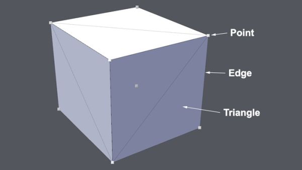
Modeller uses 3D meshes to represent the vehicle model in 3D space. All meshes are built from three basic structures - points, edges and triangles.
Points
The most elementary part of a 3D model is the point (also referred to as a vertex) which is a single point in 3D space. Points are represented in the 3D viewport in point mode as small square buttons.
Edges
An edge always connects two points by a straight line. They are used to construct triangles. Edges are represented in 3D viewport in triangle and point modes as thin lines.
Triangles
Triangles (often abbreviated to tris) are used to build the actual surface of the object. They are what you see when you render the mesh. If this area does not contain a face, it will simply be transparent or nonexistent in the actual model.
A triangle is defined as the area between three points, with an edge on every side.
Editing modes
Buttons for switching editing modes are located at the top left of the screen.
| subob | Subobject Mode |
| tri | Triangle Mode |
| point | Point Mode |
| build | Build Mode |
| map | Texture Mapping Mode |
| cutout | Texture Cutout Mode |
| page | Texture Page Mode |
| view | View Mode |
Load / save object
At the bottom left of the screen, there is a set of buttons used to load or save an object in the Modeller.
If you have an subobject selected, another row of buttons appears, allowing you to load or save the current subobject.
| subobject | Indicates that a subobject is currently selected |
| load | Load a new subobject, replacing the selected subobject |
| save | Save the current subobject as an object in data\3dob |
| main object | The name of the main object |
| LOAD | Load a new object from data\3dob |
| SAVE | Load the main object to data\3dob |
| skinXFG_DEFAULT | Click the skin name (e.g. XFG_DEFAULT) to select a JPG image in data\skins to use as a skin in the editor |
| OBJ | Load an OBJ file from data\obj |
Model view modes
View options
| This page or section is being initially created, or is in the process of an expansion or major restructuring. You are welcome to assist in its construction by editing it. |
- Show main
- Show subobs
- Show wheels
- Show hidden
- Normals
- Test L.R.swap
- Wire overlay
